Multiwire probing setup
Uses the Probe functionality to reproduce the fill-factor artifact from alternating current/voltage wires in a bifacial busbarless multiwire measurement.
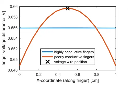
This example uses Quokka3’s Probe functionality to simulate the fill-factor artifact that arises when alternating current and voltage wires are used to measure a solar cell. The modeled device is a bifacial busbarless cell with alternating current/voltage wires at 5 mm spacing. The Probe functionality defines a voltage for the JV calculation that differs from the default applied voltage, thereby representing a 4-wire measurement.
Interactive 3D model — rotate, pan, zoom.
The simulation shows that the maximum voltage occurs precisely at the voltage-sense wires, because current flows along the fingers toward the current wires. When fingers are highly conductive this maximum can exceed the mean voltage, leading to overestimated FF and efficiency; more poorly conductive fingers (higher Rsheet) can actually increase the measured efficiency in such a setup.
What this example covers:
- The Probe functionality for representing 4-wire measurements
- A bifacial busbarless cell with alternating wires at 5 mm spacing
- How finger conductivity (Rsheet) biases measured FF and efficiency
Resources